Pressure Testing & Vacuum Testing

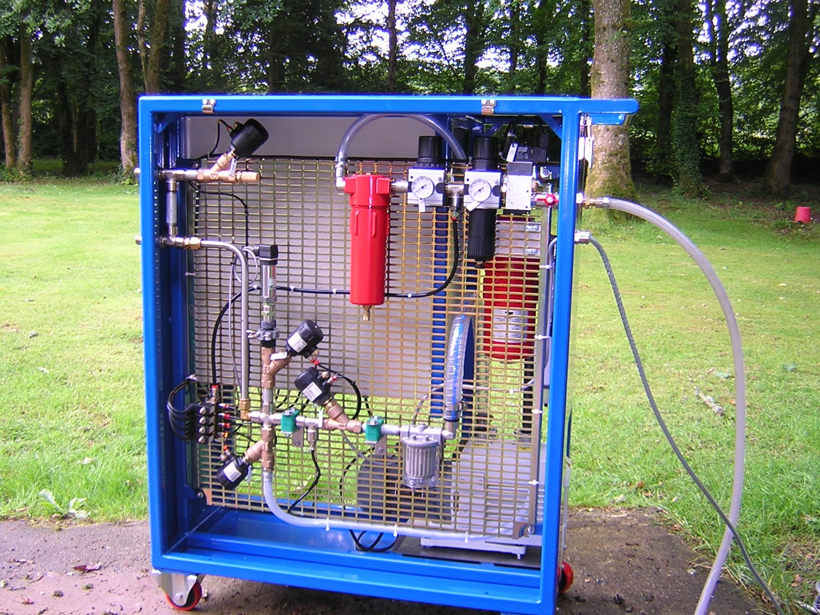
This is a dual pressure and vacuum test machine supplied to TIM in France who manufacture "Cabs" for agricultural and construction vehicle manufacturers in the UK and Europe. The machine in question connects to the cab portion of the vehicles air conditioning system and performs two tests the first was to pressurise the system with conditioned compressed air to check the integrity of the system ie all the pipes are attached, the swivel nuts screwed onto the male thread etc. Once the machine registers that the system is complete it is vacuumed to 1 mBar and then checked for very smal leaks ie a swivel nut is only finger tight or theres apin hole in the braze on the evaporator using vacuum decay method of checking. With the system being tested being an air conditioning system then the vacuum is left in it to prevent moisture ingress.
Leak testing of components is achieved primarily in two basic ways either by vacuum or pressure testing.
Vacuum testing relies on the rise in detected pressure as a result of a leak ie a vacuum of 999 mBar is recorded on an component, the vacuum is isolated from the component then a period of time later (10 seconds for example) the vacuum level is recorded. If the recorded level is the same ie 999 mBar or only reduced by a known amount ie 990 mBar the component can be termed leak tight or has a leak rate less than the set specification of 2 mBar per second for example.
Pressure testing by what is termed pressure decay works exactly the same as vacuum testing but in reverse so for example the component is tested with 6 Bar pressure (6000mBar), 10 sec later the pressure is recorded again 6000mBar for example, so is termed leak tight but there are a number of physical phenomena that has to be considered:-
- When air flows through an orifice ie a pipe, a fitting or reservoir heat is generated into the air and this affects the recorded pressure reading.
- Pressurising a component causes an increase in volume which affects the recorded pressure reading.
- When a leak specification is given it nearly always is expressed as XX Mbar/second or minute and when the pressure recorded is considered it is usual to check that the two readings are within the specification. However this fails to produce accurate results as if the component has 10 leak source points for example then the recorded pressure has to be 1/10 of the specification to ensure that a leak is detected at a leak source.
We have developed and manufactured equipment that removes these problems and is able to detect a leak at much reduced process testing time. The method used is generally referred to as air replacement and this test method is extremely effective when only low pressure can be used due to the materialised for the construction of the component or expansion in the case of fuel tanks. Testing on a plastic bottle of 20 litre volume we are able to test for a leak equivalent to 0.25mm in diameter in 8 seconds.